System architecture
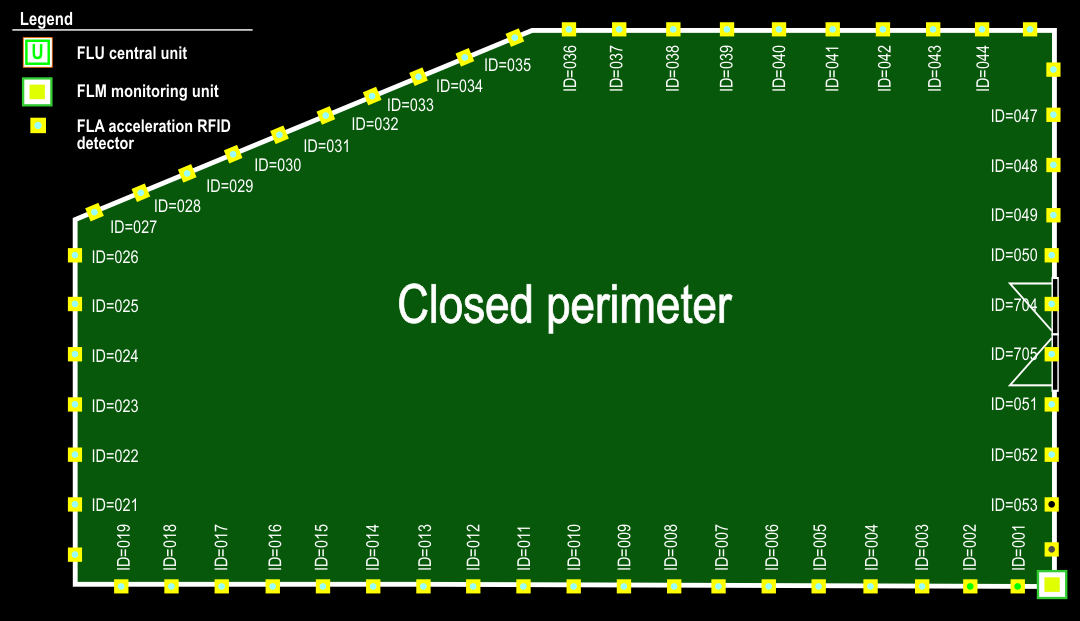
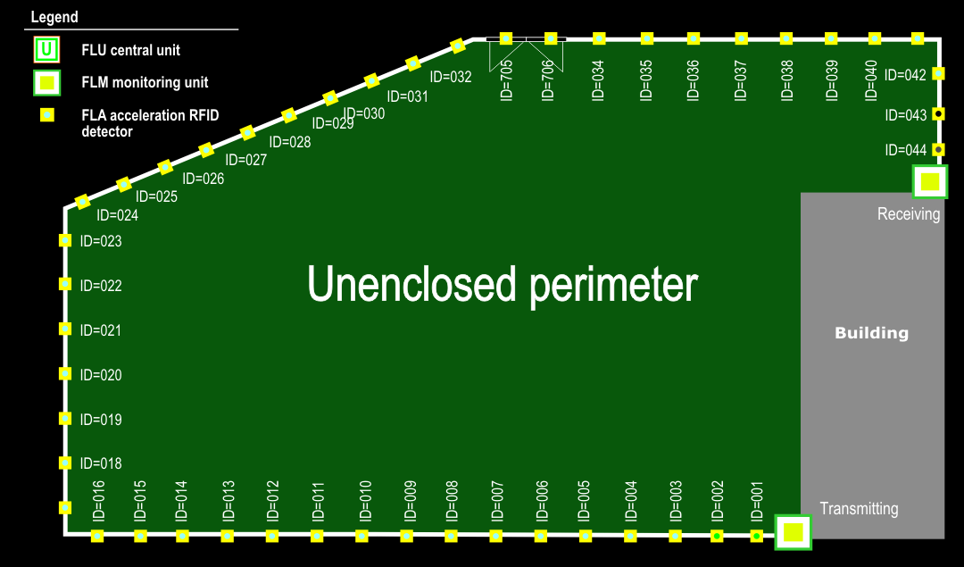
The core of the Varya Perimeter system consists of FLU central unit, one or more FLM monitoring units, FLA detectors and possibly also FLG detectors.
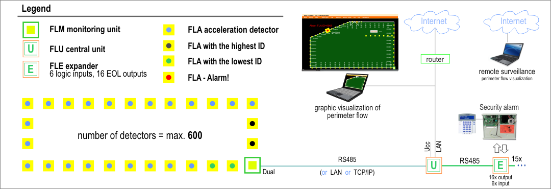
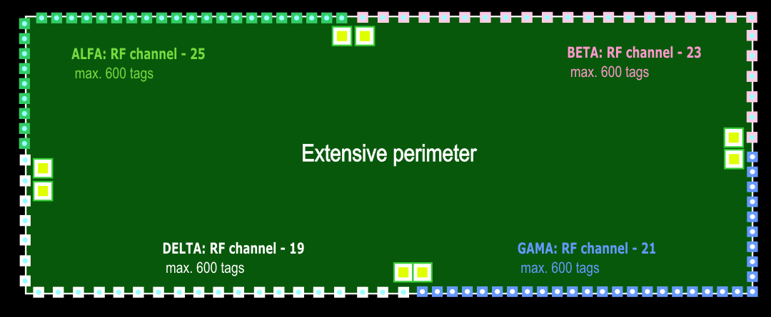
The system may be closed (see Figure 7) or unclosed (see Figure 8), which determines the number of FLM units needed. The FLM monitoring unit communicates with the first two and last two FLA detectors and is wired to the FLU central unit via RS485 bus or LAN. If the logical outputs on the central unit are not sufficient, the FLE or FLQ expanders can be used, allowing connection to IAS via logical inputs and outputs. The IAS sends the perimeter system information on which areas are to be guarded/unguarded, and in turn the perimeter system sends to the IAS the information stating in which areas a breaching of the perimeter, sabotage, malfunctioning, etc. has occured. The entire system is configured via the Varya Perimeter software and allows remote supervision and monitoring via the Internet. The maximum number of detectors in the system is 600.